Multistate alarm delay examples

When attaching alarm extensions to binary objects, we recommend that the alarm extension be attached to a Binary Input Object (BI). When the Binary Output Object (BO) is commanded On, the command is seen by the command reference of the BI and triggers the Alarm State: Reference Delay Timer, which changes the Normal state of the associated BI. The Reference: Input of the BI should change to match the new Normal state during the time set by the Alarm State: Reference Delay Timer. If it does not, the BI immediately goes into Alarm upon expiration of the Reference Delay Time. If the BI Reference: Input changes to match the new Normal state, then the Alarm State: Report Delay Timer starts. The Alarm State: Report Delay time does not delay delivery of a previously generated report. It delays the analysis of the BI object for an alarm condition until the Report Delay time has passed. Once the Report Delay time passes, the BI is analyzed for Alarm conditions.

For example, with a BO controlling a fan and a BI with an Alarm Extension set using the BO as an Input reference, two possible conditions are affected by the Alarm State delay timers:

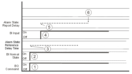
  1. Fan on and operating normally—In the following figure, a fan has been commanded On and is operating normally. In this case, when the BO commands the Fan On, the Normal State of the BI changes to On and the Reference Delay Time starts. Within the interval set by the Reference Delay Time, the Input Reference of the BI changes to On and the Report Delay time starts. After the Reference Delay Time and Report Delay Time have passed, the BI is analyzed for Alarm conditions.
    Figure: Fan on and operating normally


    Table 1. Fan on and operating normally example description
    Number Name User action
    1 BO Command Fan is commanded On from BO.
    2 BI Normal State BI Normal State switches to On.
    3 Alarm State: Reference Delay Timer Reference Delay Timer interval starts when BI Normal State switches to On.
    4 BI Input BI Input switches On during the Reference Delay Timer interval.
    5 Alarm State: Report Delay Report Delay interval starts when BI Input switches to On.
    6 After Report Delay Interval BI is analyzed for alarm conditions.
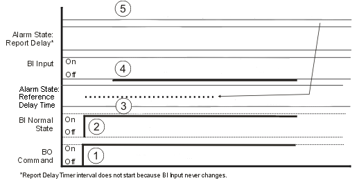
  2. Fan is commanded On but the fan is not working—In the following figure, the fan is commanded On but does not turn on due to a problem. In this case, the BO commands the Fan On, the Normal State of the BI changes to On, and the Reference Delay Time starts. However, the Input Reference of the BI never changes to On because the Fan does not turn on. Therefore, the Alarm State: Report Delay Timer never starts. After the interval set by the Alarm State: Reference Delay Time expires, the BI goes into an Alarm condition.
    Figure: Fan is commanded On but the fan is not working


    Table 2. Fan is commanded On but the fan is not working description
    Number Name User action
    1 BO Command Fan is commanded On from BO.
    2 BI Normal State BI Normal State switches to On.
    3 Alarm State: Reference Delay Timer Reference Delay Timer interval starts when BI Normal State switches to On.
    4 BI Input BI Input does not turn On during the Reference Delay Timer interval due to problem with Fan.
    5 Alarm State: Report Delay After Reference Delay Timer interval. BI is analyzed and goes into Alarm.