Floor Plan
What are the available Floor Plan symbols?
 Status Summary |
 Room Control Module (Multiple Rooms) |
|
What are the Property panel properties and the Binding properties available on the Status Summary symbol?
The Status Summary symbol has an Orientation (Horizontal or Vertical) property in the Property panel.
The Status Summary symbol displays the number of alarms, warning statuses, and points from equipment serving the space bound to the Status Summary symbol that are offline or inaccessible. You can drag any space into the Space binding field.
After you save a new graphic with a Status Summary symbol, you can view it in the Graphics widget. When you move your cursor over the Status Summary symbol, a tooltip displays the number of alarms, warning statuses, and points that are offline or inaccessible. When working with a graphic created in an earlier version of the Metasys UI, first edit and then save the graphic in the Graphics Editor. The tooltip displays the number of alarms, warning statuses, and points that are offline or inaccessible only after you edit and save older graphics.
When you bind the Status Summary symbol to a space, the number of alarms, warning statuses, offline, and value inaccessible statuses display at view time in the Graphics widget. If the Include first level child check box is selected, the count includes statuses from points for the space bound to the Status Summary symbol and its first child space. If the Include first level child check box is not selected, the count includes statuses from points for the space bound to the Status Summary symbol only.
| Binding | Short Name | Animation Available |
|---|---|---|
| Space | No | |
| Include first level child | N/A | No |
| Filter 1 | No | |
| Filter 2 | No | |
| Filter 3 | No | |
| Filter 4 | No | |
| Filer 5 | No | |
| Navigation | No |
What additional information is available for the Room Control Module? What are the Binding properties available on the Room Control Module symbol?
- Start with a Metasys UI graphic that has a floor plan image or similar image added to the graphic.
- Draw a path shape around the room you plan to have the Room Control Module display data for. For more information on drawing a path shape, see What is the Path tool and how do I use it?.
- Select the path shape. In the Edit toolbar, click
 .
Select the Enable Room Control property.
 - Add the Room Control Module on the Graphics Canvas.


The Room Control Module displays View Equipment if the path shape is bound to an equipment. Or the Room Control Module displays View Space if the path shape is bound to a space.
For the Room Control Module to have data, the bound point must have alarm extensions with alarm limits and a setpoint configured. If the bound point has more than one alarm extension, the Room Control Module uses the first alarm extension. The alarm extensions are configured and the order of alarm extensions is set in SMP or SCT.
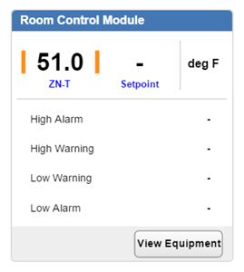
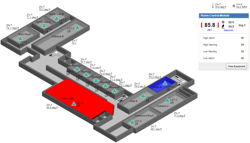
The Room Control Module shows the bound point value and status, the setpoint, and the unit in the top area of the Room Control Module. To populate the Room Control Module at view time, you must tap or click on the Room Control Module in the Graphics widget. The Room Control Module does not dynamically update for certain data values. However, the setpoint, value, and warning limits dynamically update. You must tap or click the path shape to populate the alarm limits.
The Room Control Module lists High Alarm, High Warning, Low Warning, and Low Alarm for the bound point. The bound point must have an alarm extension for this data to populate.
When you hover over the Room Control Module on a computer platform, the shapes drawn with Path tool highlight (only if a point or navigation is bound and the opacity is set to 100% on mouse over).
